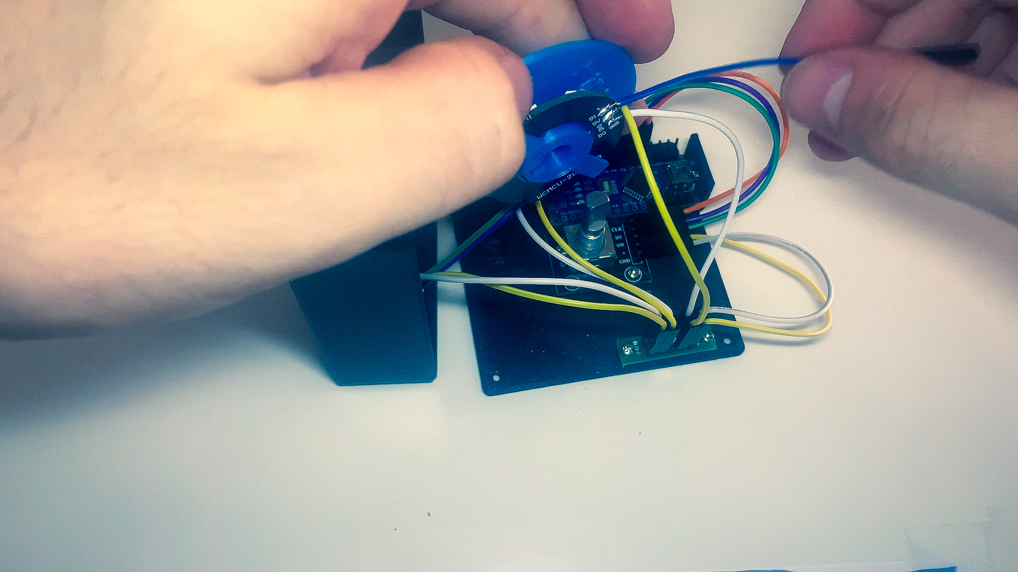
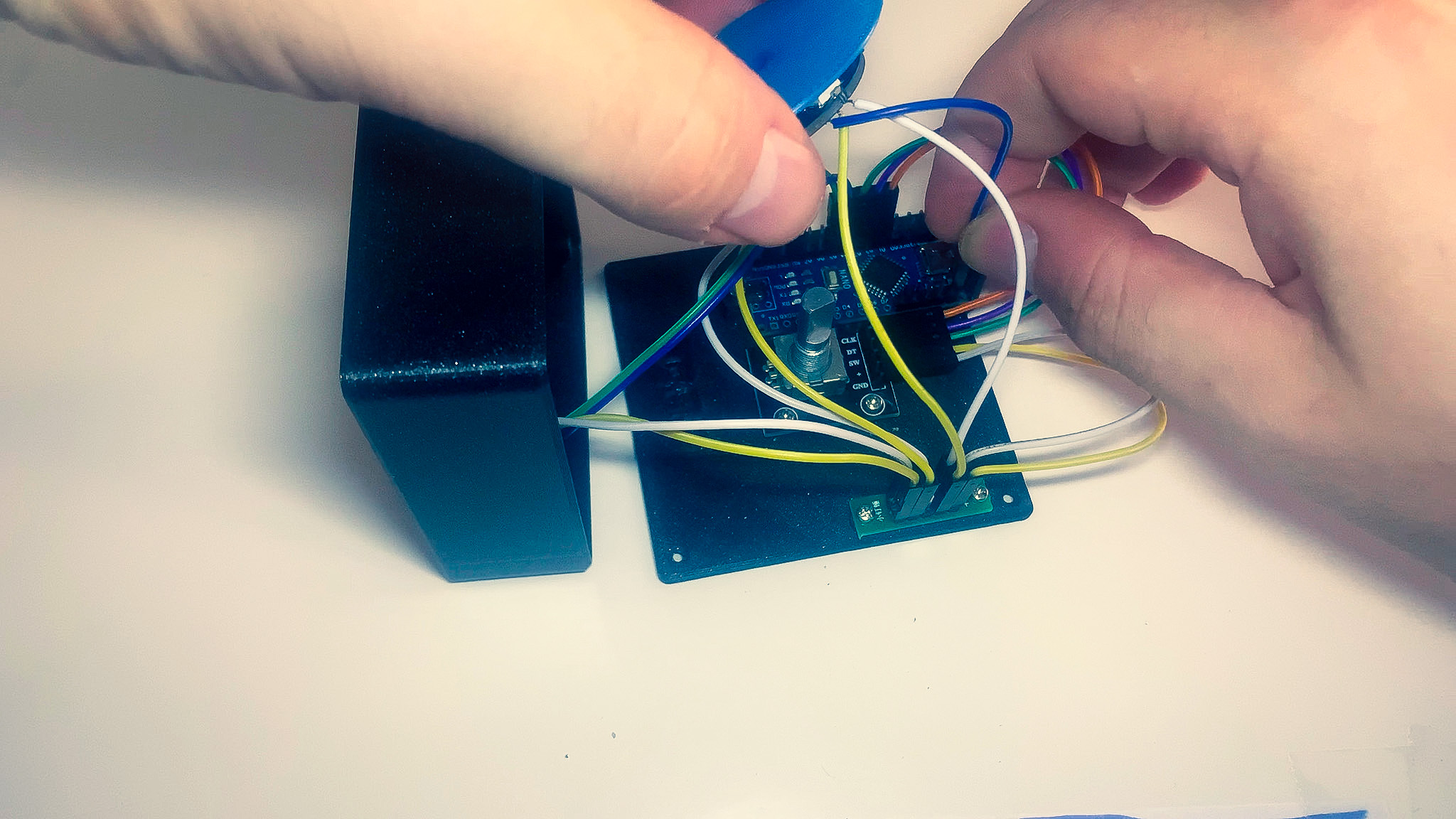
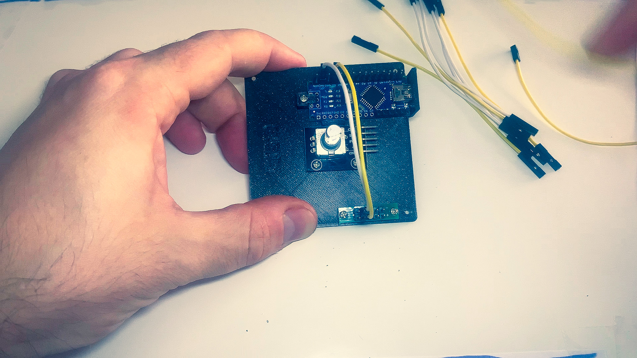
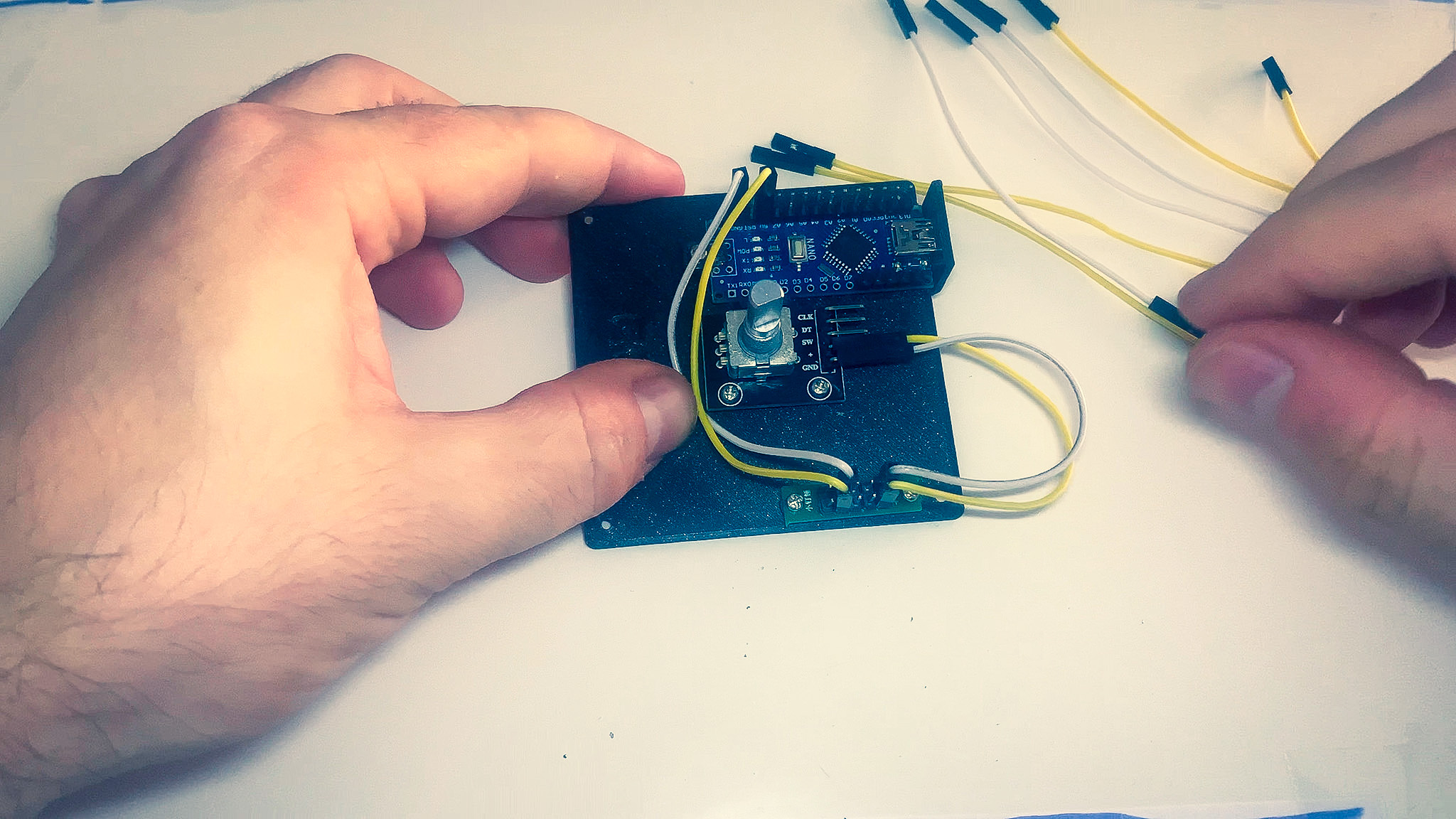
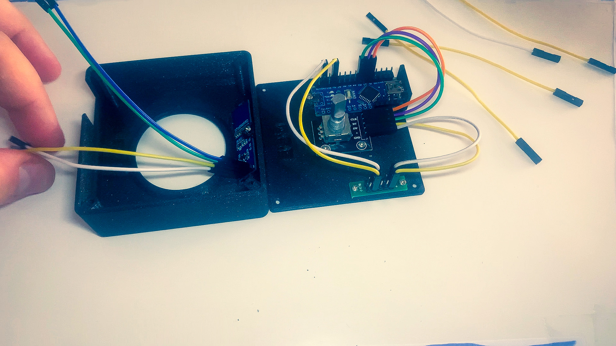
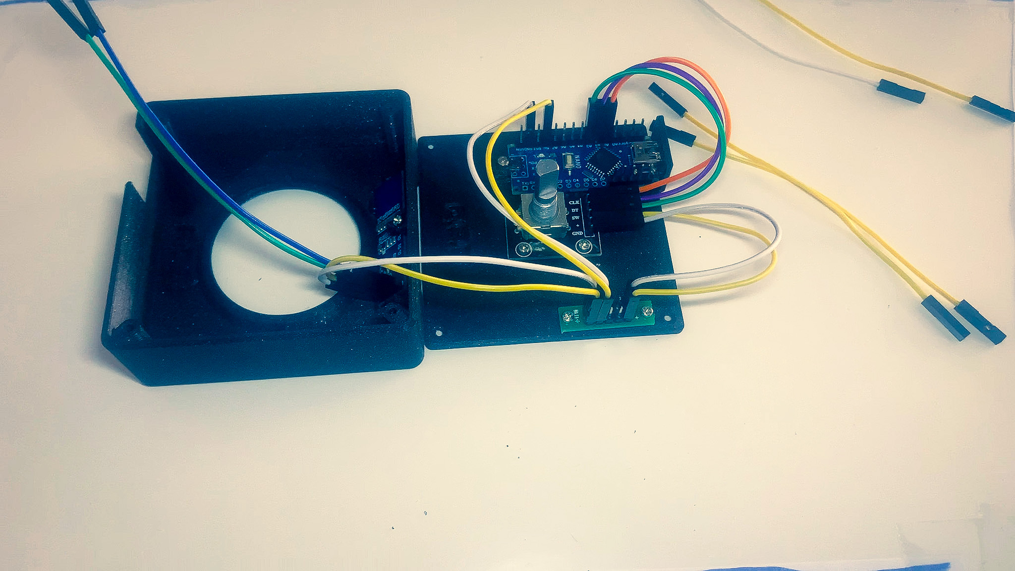
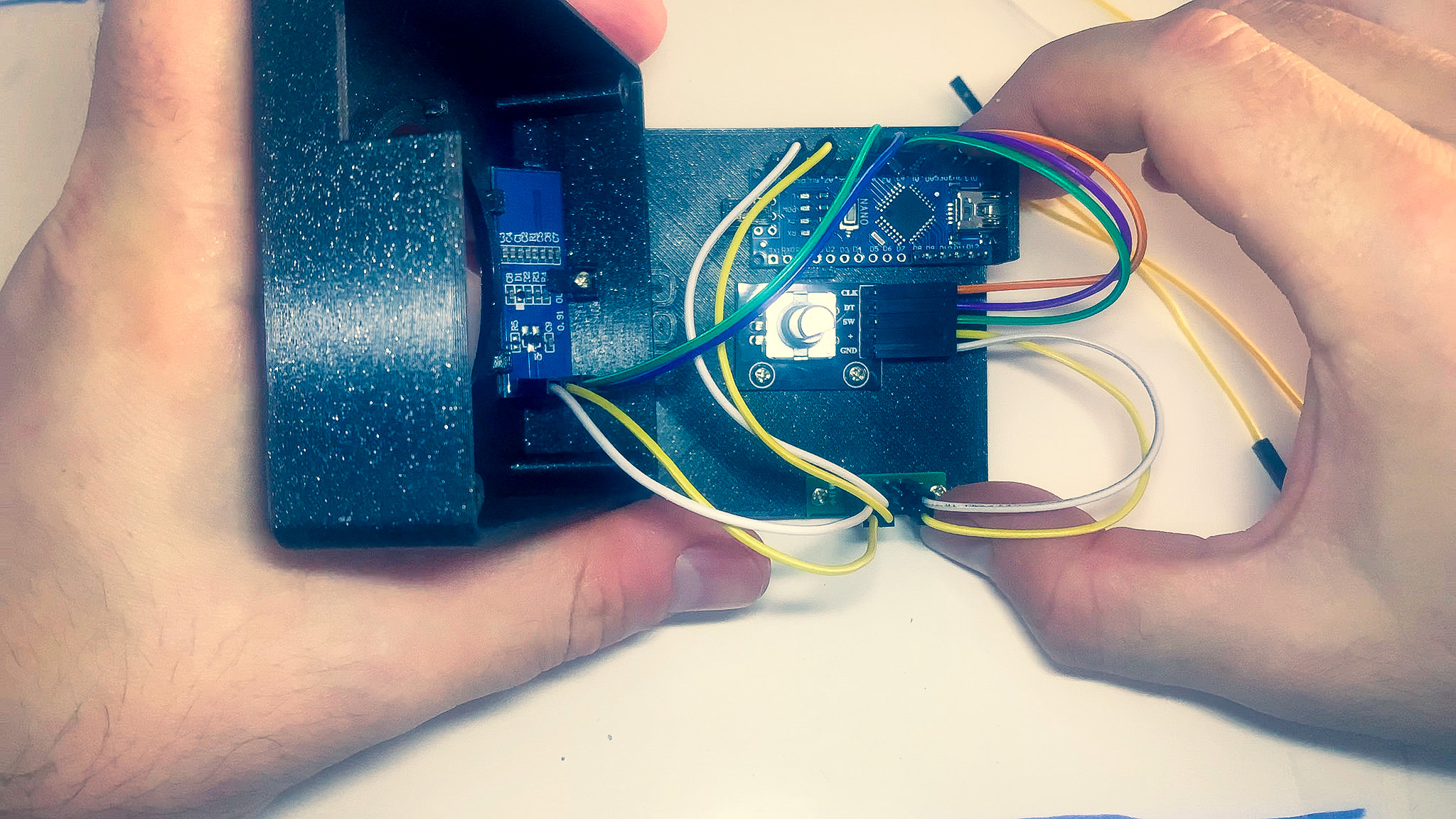
Wiring
Connecting wires incorrectly will destroy electronic components.
MCU
Use the table below to connect the wires between the MCU and the power bus.
| MCU | Power bus |
|---|---|
| GND | - |
| 5V | + |
Rotary encoder
Use the table below to connect the wires between the MCU, rotary encoder and power bus.
| Rotary encoder | Power bus | MCU |
|---|---|---|
| GND | - | |
| + | + | |
| SW | A3 | |
| DT | A2 | |
| CLK | A1 |

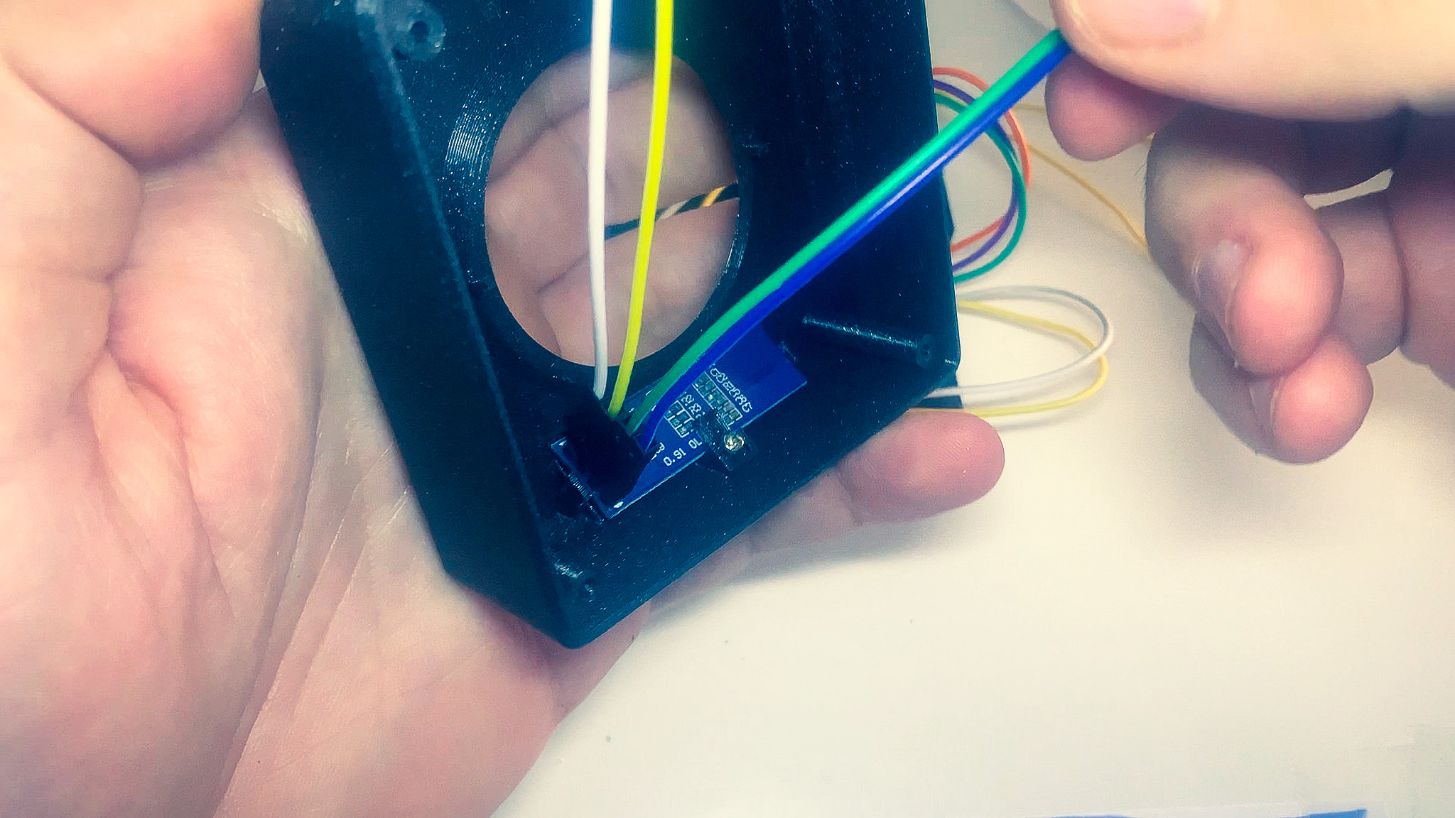
Display
Use the table below to connect the wires between the MCU, display and power bus. The pins of the display are numbered from top to bottom.
| Display | Power bus | MCU |
|---|---|---|
| (1) GND | - | |
| (2) VCC | + | |
| (3) SCK | A5 | |
| (4) SDA | A4 |
LED Ring (Optional)
Use the table below to connect the wires between the LED ring, MCU and power bus. The pins of the display are numbered from top to bottom.
| LED Ring | Power bus | MCU |
|---|---|---|
| GND | - | |
| VCC | + | |
| DI | D12 |